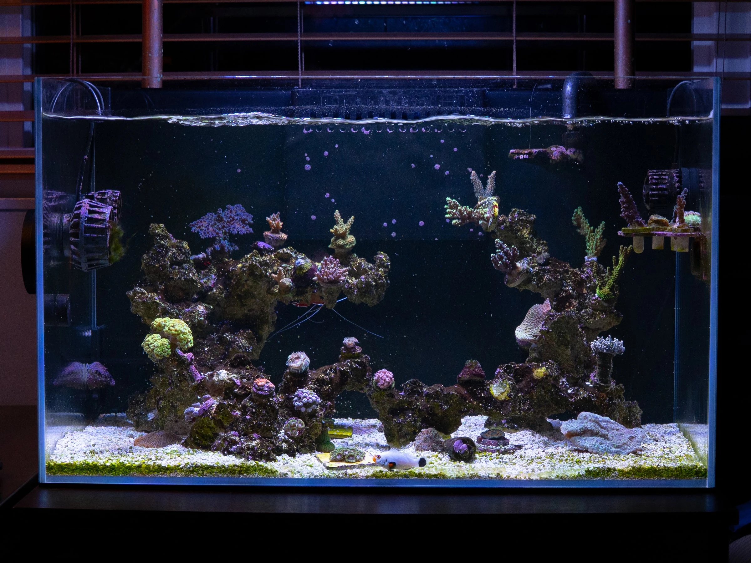
UNS 60U Reef System
A 30-gallon closed-loop reef system I modeled in Fusion 360, then built.
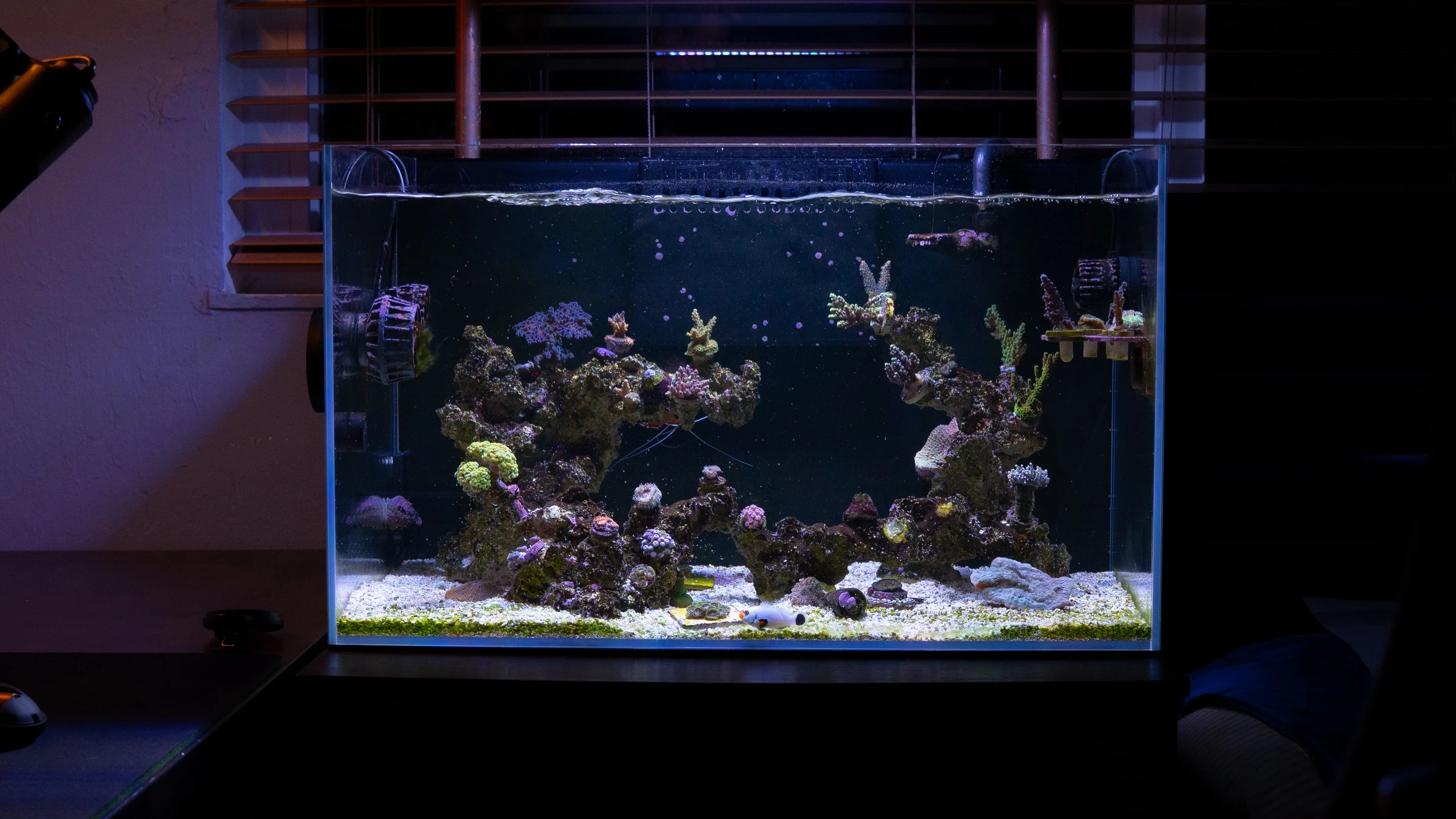
- What it is
- A complete reef system built around a UNS 60U tank, covering the stand, sump, plumbing, and an equipment bay beside the stand. About 30 gallons total.
- My role
- Designer and builder. I modeled the whole system in Fusion 360, then built it.
- Tools
- Fusion 360, DXF export for cutting, PVC pipe and fittings, Silicone (sump baffles), 1/2 in plywood, Kreg pocket-hole jig, Miter saw, Hand saw, Clamps, Sandpaper, Stain
- Timeframe
- August–September 2026
01 The problem
A reef tank needs plumbing, filtration, and equipment to keep the water clean and stable. My system and all its equipment had to fit between my bed and my desk, and cost less than $350. The plumbing had to run as a closed loop, so all water leaving the tank returns to it, and a power outage couldn't flood the floor.
02 Design
Water moves through the system in one loop:
- Overflow. An overflow box skims water off the top of the display tank.
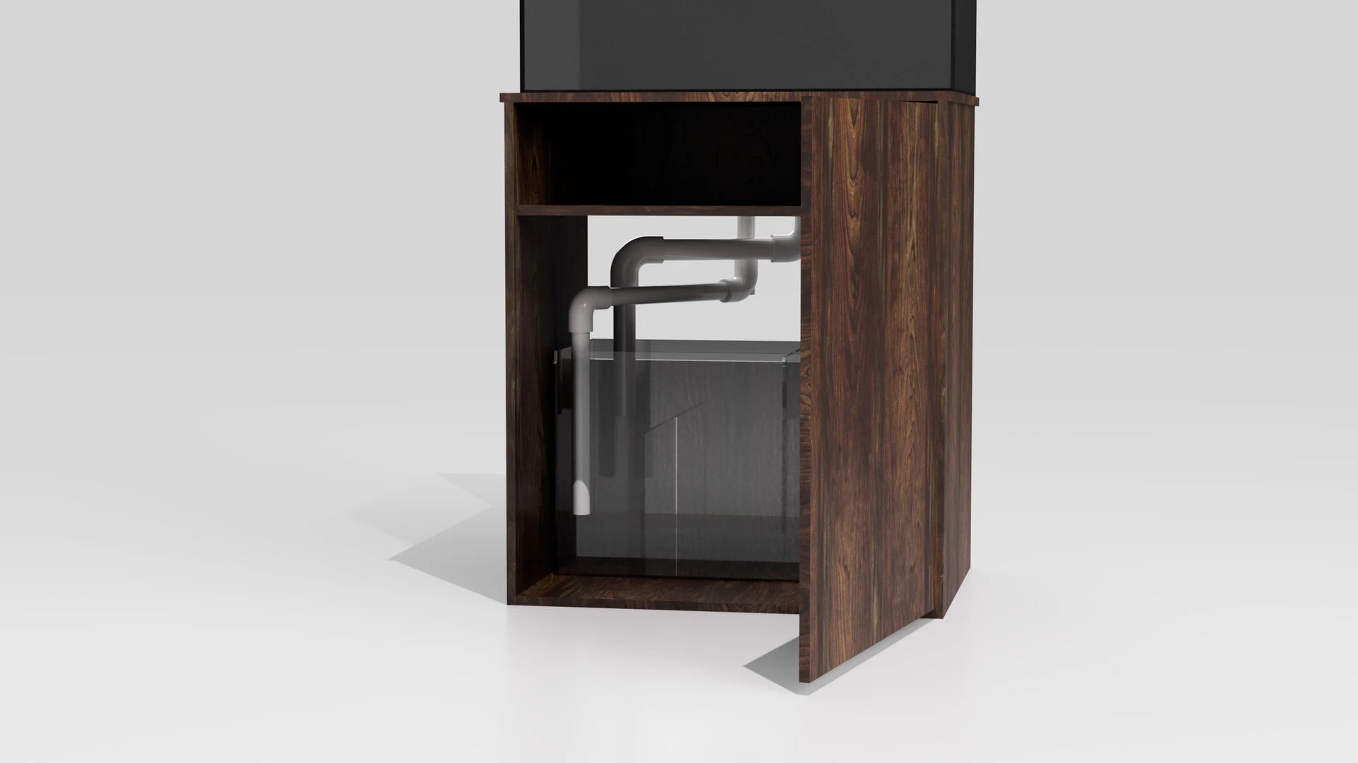
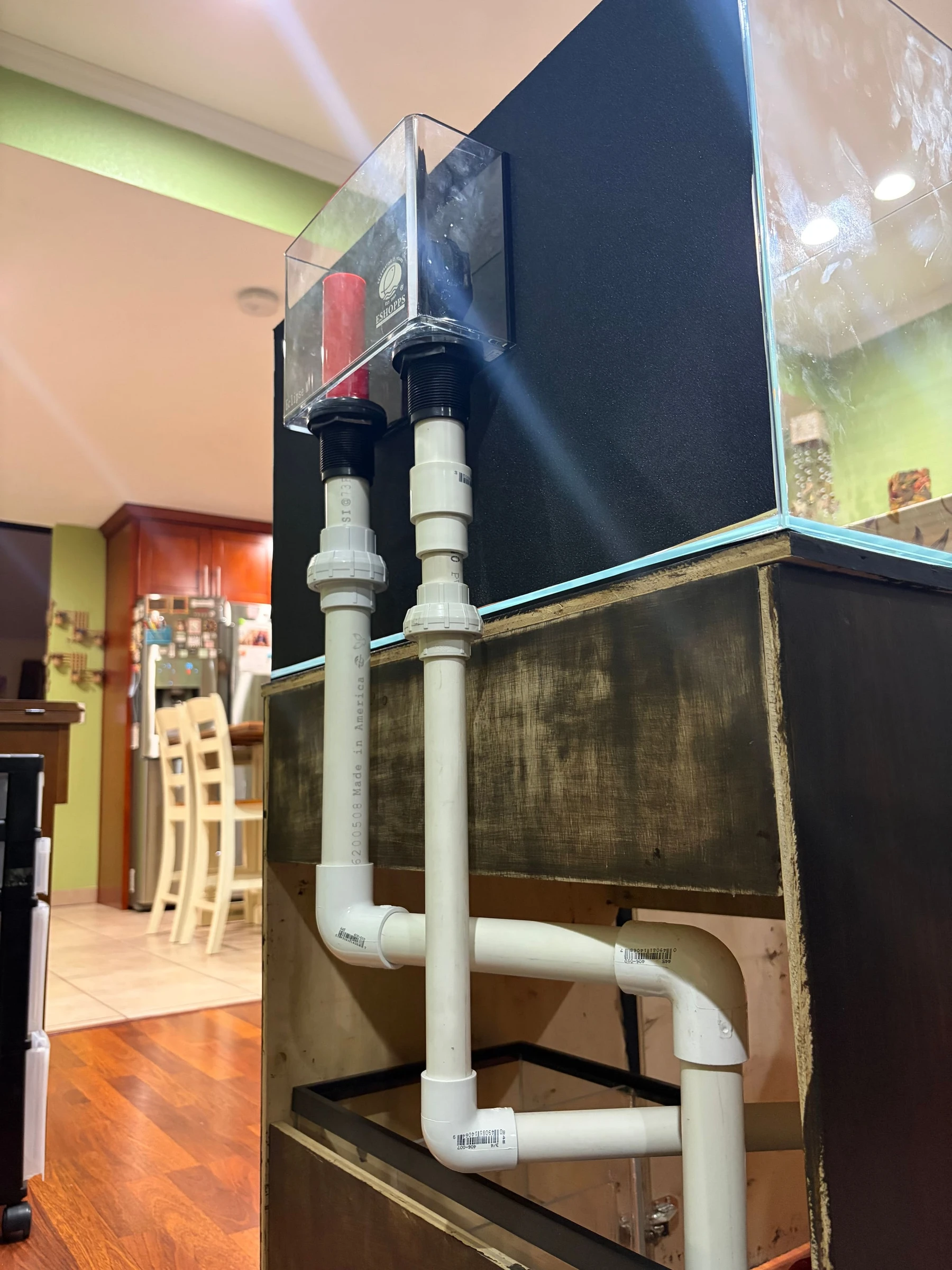
- Drain. Two PVC lines carry it down to the sump, a second tank under the display that holds equipment. The second line has an emergency standpipe: a backup in case the main drain clogs.
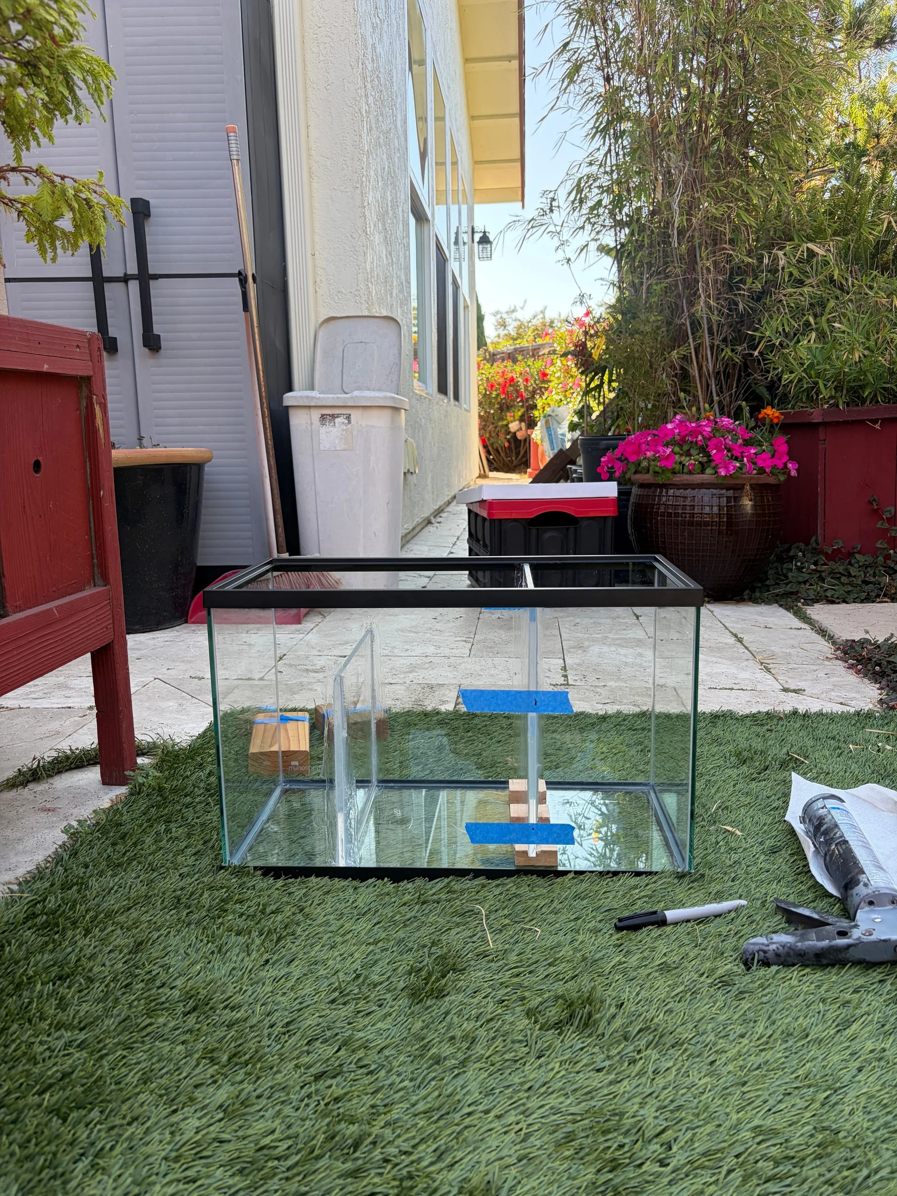
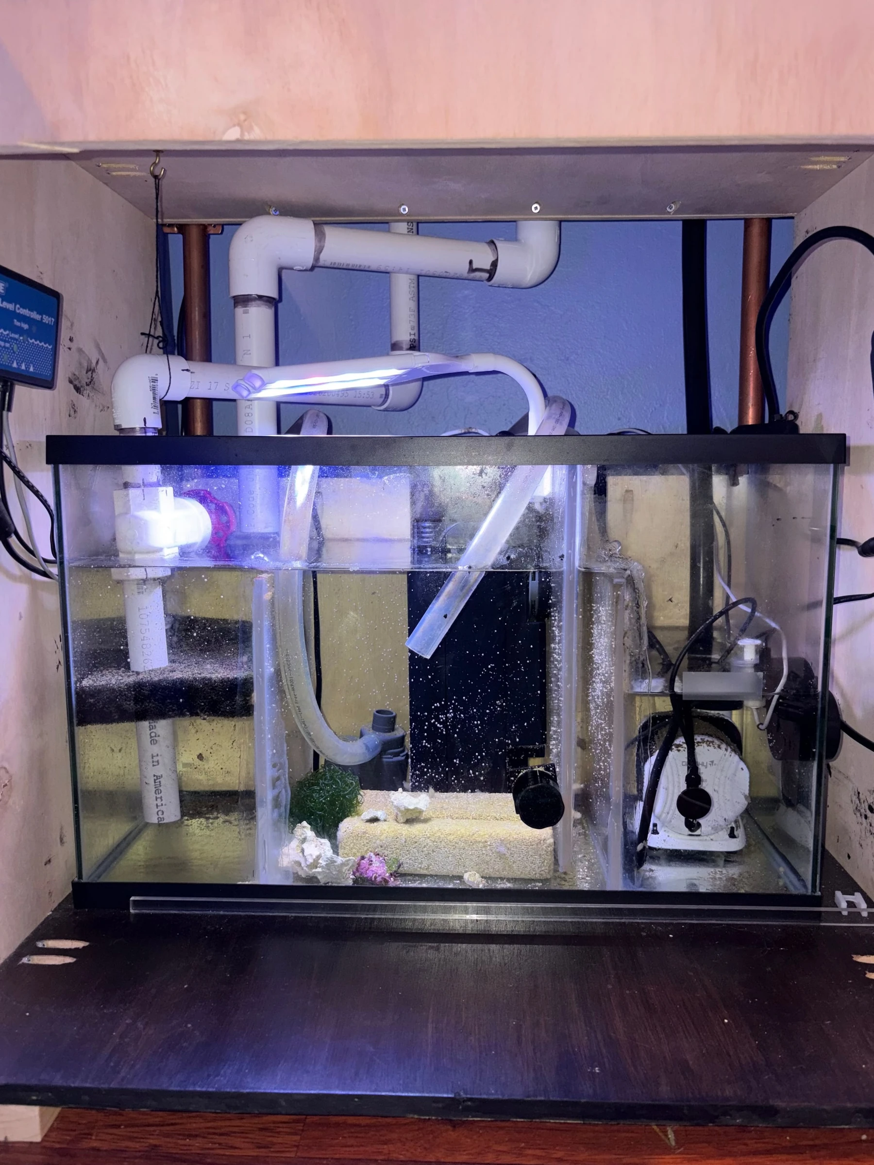
- Sump with custom baffles. Baffles (walls inside the sump) split it into chambers, so water passes through each stage in order: mechanical filtration, then skimming and the refugium, then the return.
- Return line. A pump sends clean water back up to the display tank.
A second, pump-fed loop runs water through an inline UV sterilizer. It lives in an equipment bay beside the stand, along with a dosing pump and the power strip.
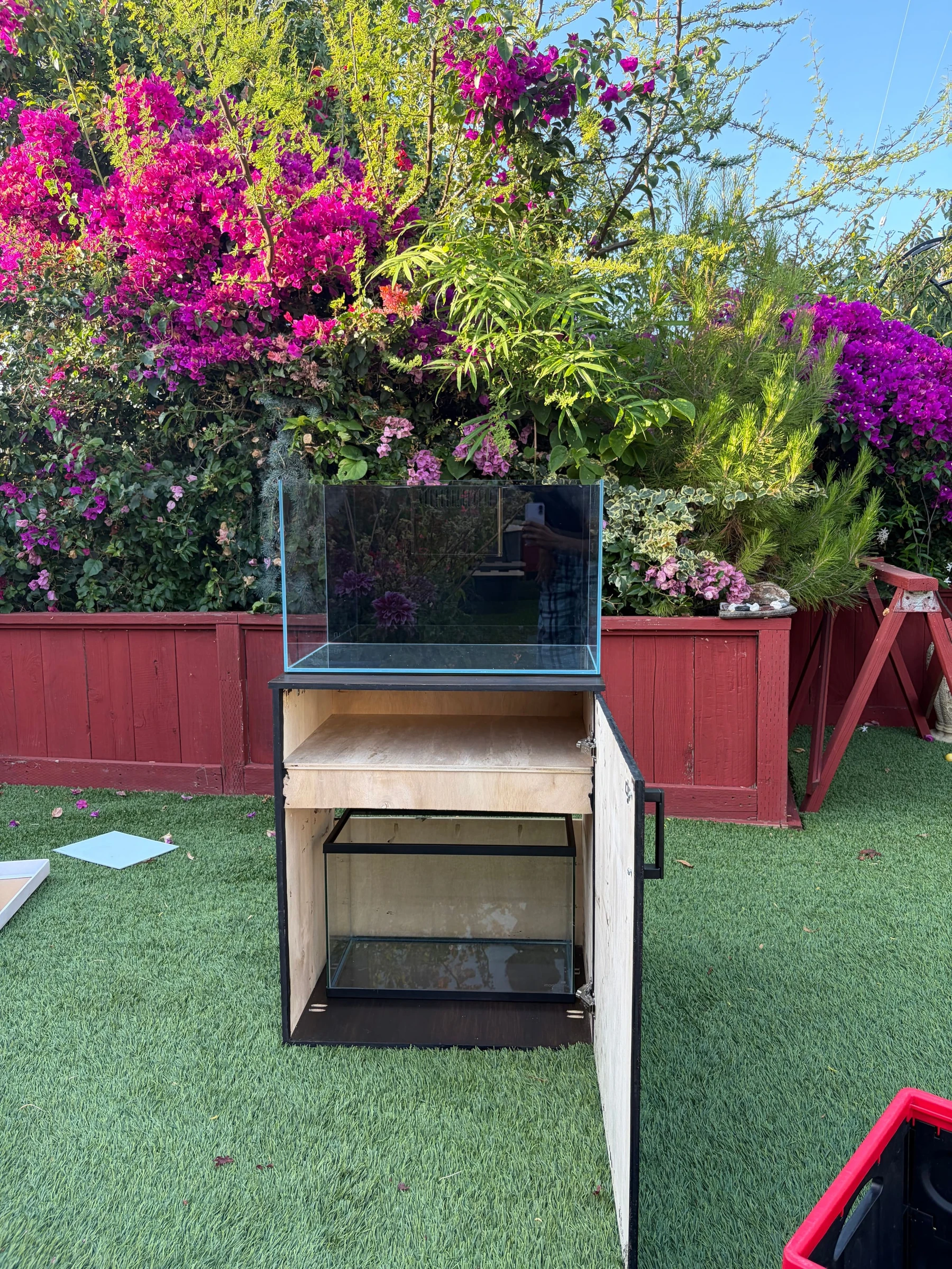
The stand. I built the stand from 1/2 in plywood, joined with Kreg pocket holes. The top rests directly on the side panels, and the tank sits right over those sides, so its weight transfers straight down instead of loading the joints. L brackets reinforce the joints in shear, and the shelf is there more for twist rigidity than for storage. I sanded and stained it to finish.
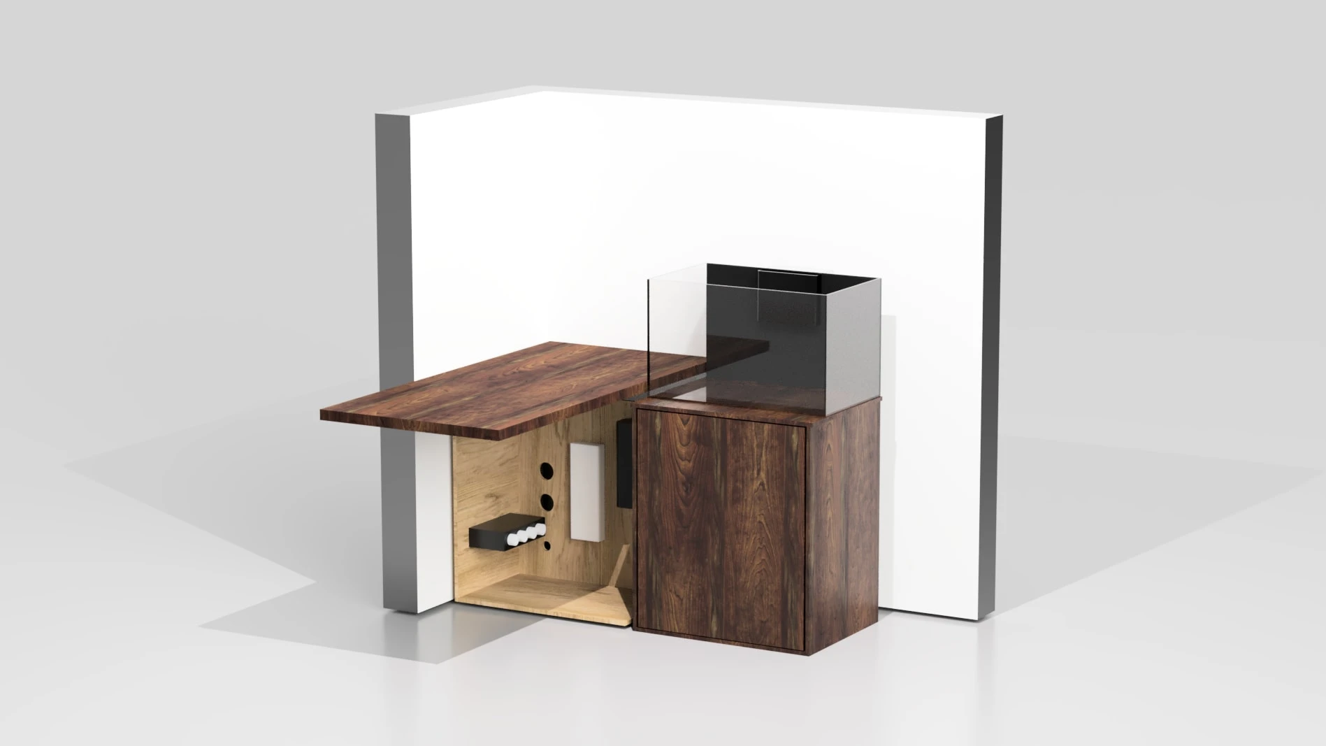
Why a separate equipment bay. Saltwater and electronics don’t mix, and keeping things clean under my desk was a necessity. I designed the separate bay to keep the inside of the stand clean, to keep the water and the electronics apart, and to leave room for future equipment like auto testers.
Planning for a power outage. When the pump stops, water in the return line can siphon backward into the sump. A siphon break lets air into the line to stop that flow early, which limits how much water drains down. Mine is a small hole in the return line, 0.25 in below the waterline, so about 0.34 gal drains back (see the numbers below).
Full assembly
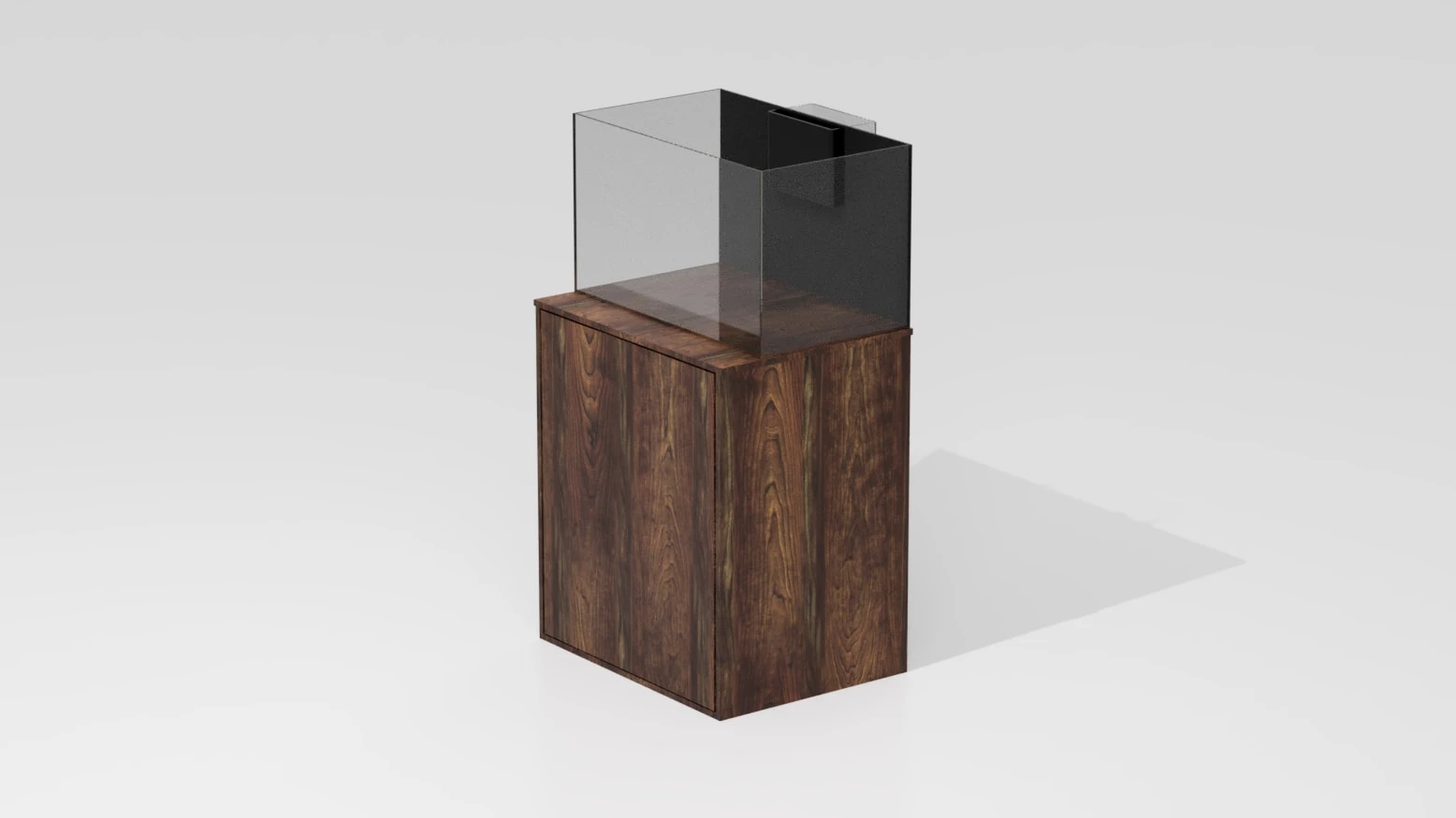
The UNS 60U on its stand, doors closed.
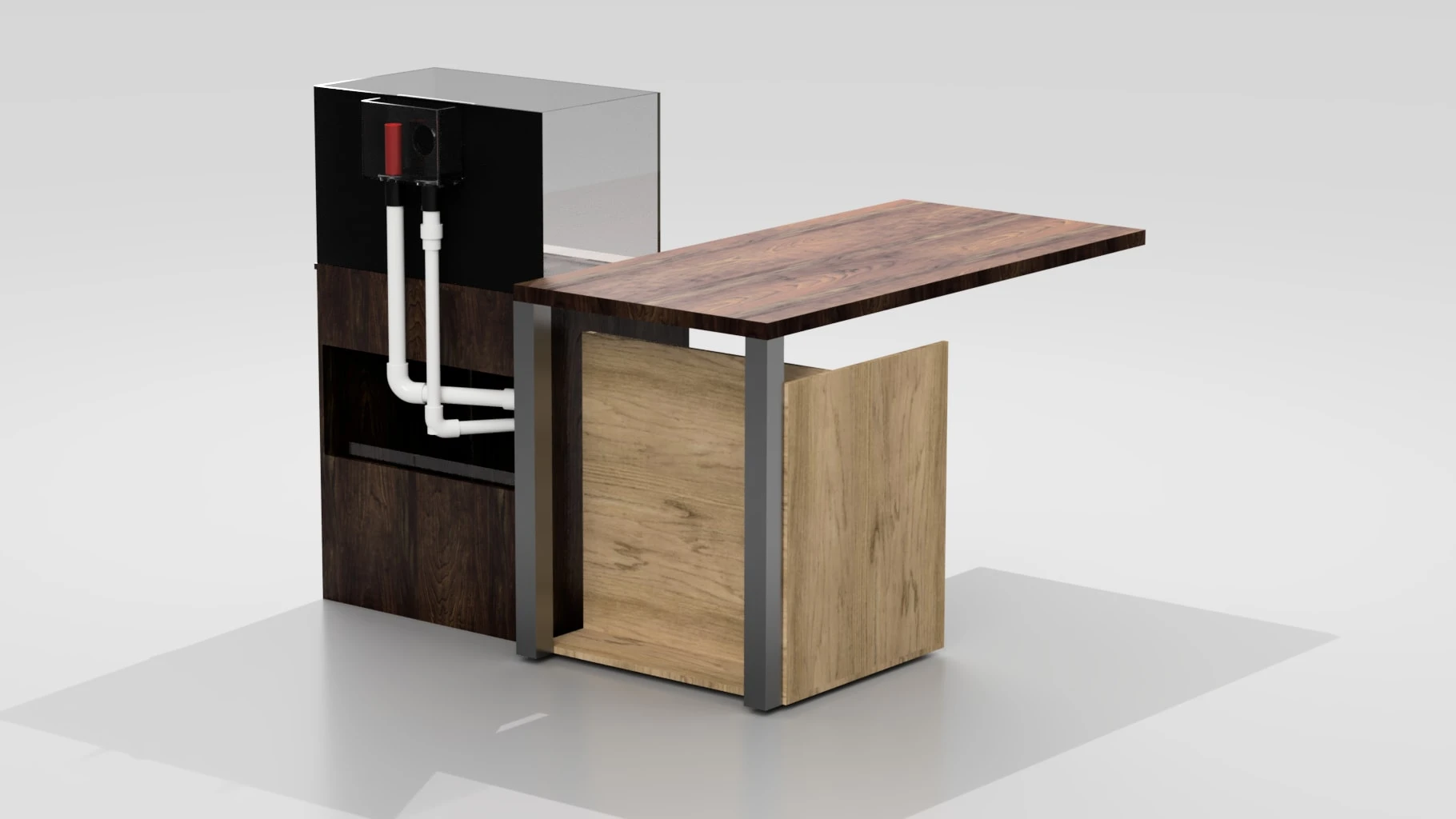
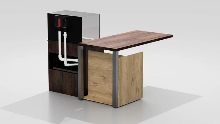
The full system in place. Tank, stand, and the equipment bay under the desk beside it.
Door open. Two drain lines come down from the tank into the sump under it.
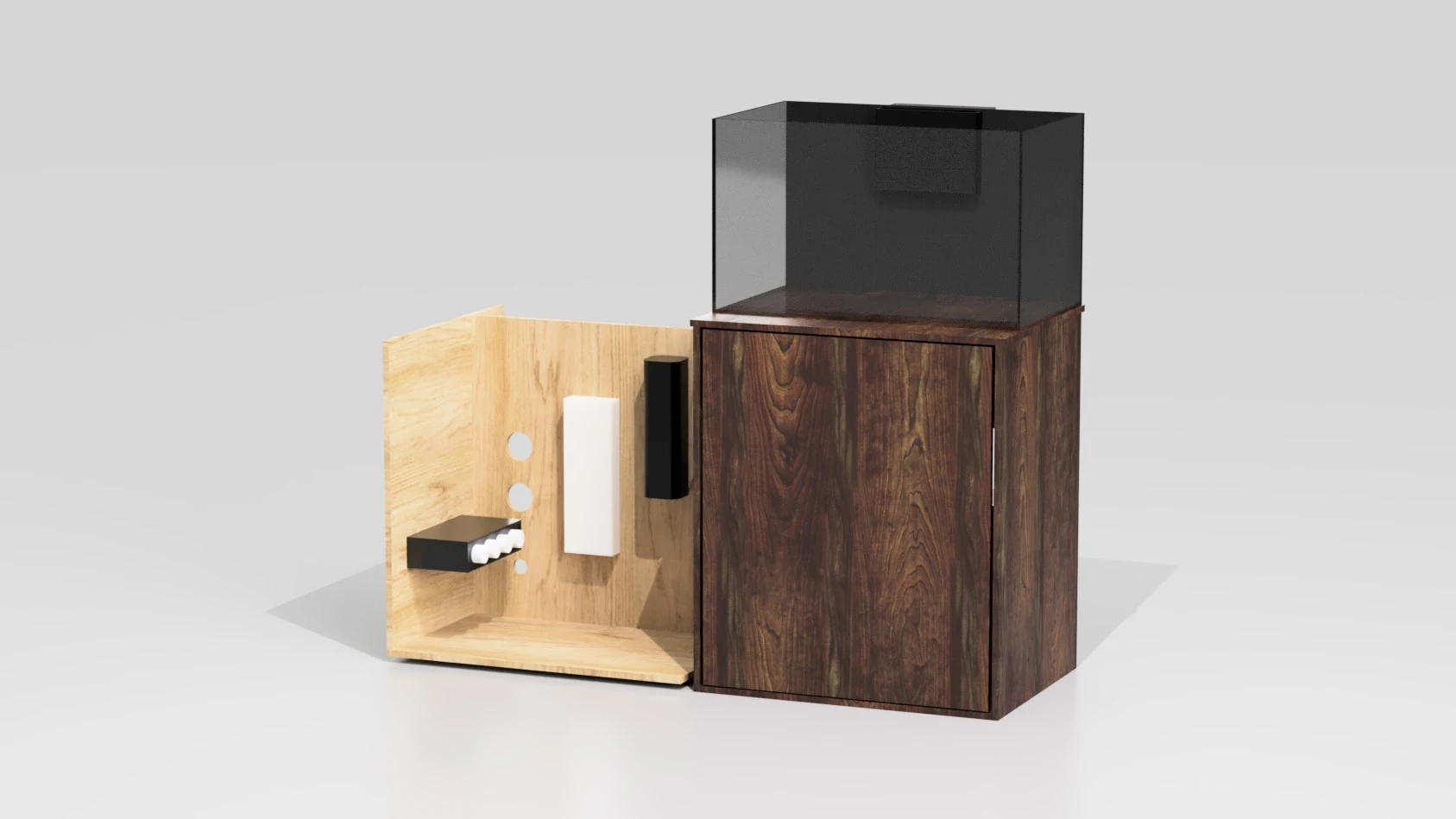
The stand with the equipment bay beside it, desk hidden.
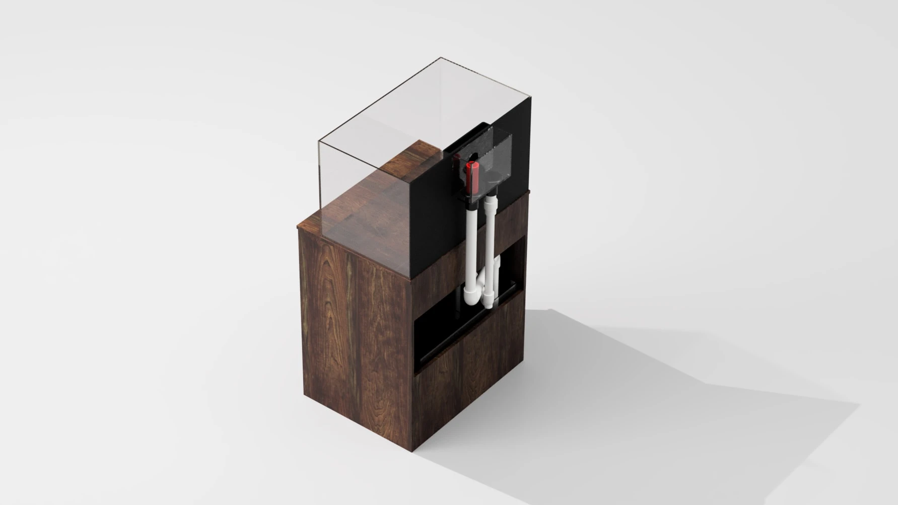
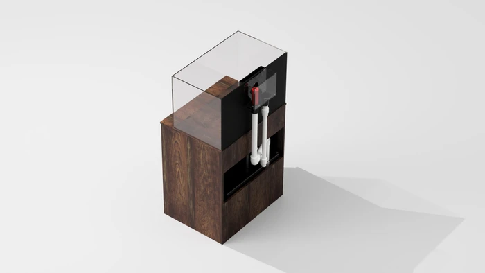
Rear view. Two drain lines run from the overflow box down to the sump. The red pipe is the emergency standpipe.
The same plumbing from a higher angle, without the desk.
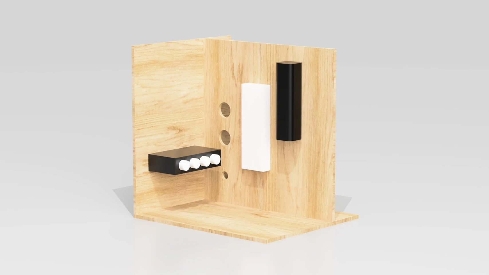
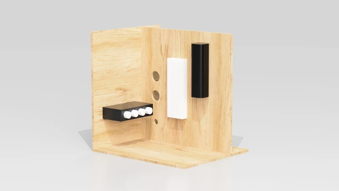
The equipment bay. Dosing pump, power strip, and UV sterilizer.
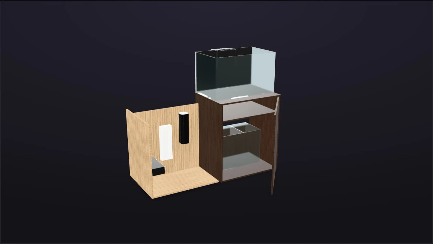
Drag to rotate, pinch or scroll to zoom. On a phone, “View in your space” shows it in AR.
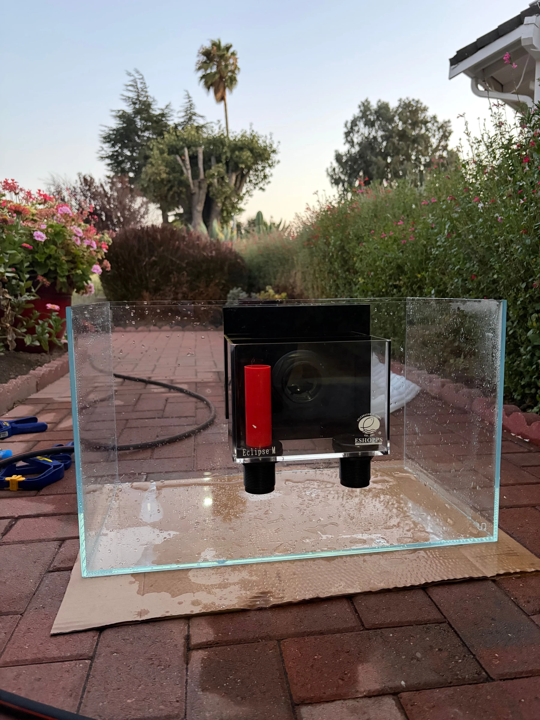
- Overflow box (Off-the-shelf)Water skims off the top of the tank into this box, then falls into the drain lines. It's an off-the-shelf Eshopps Eclipse M.
- Emergency standpipe The red pipe. A backup drain, so if the main drain clogs, rising water goes down this pipe instead of over the rim.
- Drain lines Two PVC lines carry water from the overflow box down to the sump.
- Sump A second tank under the display that holds equipment. Water flows through it, then gets pumped back up.
- Sump baffles Acrylic walls that split the sump into chambers, so water passes through each stage in order.
- UV sterilizer Part of a separate pump-fed loop. Water runs past UV light, which kills free-floating algae and bacteria.
- Stand I built it from 1/2 in plywood with Kreg pocket-hole joinery. The top rests directly on the side panels and the tank sits right over them, so the weight goes straight down into the sides. L brackets reinforce the joints that see shear, and a shelf adds twist rigidity.
- Return line The return pump sends clean water from the sump back up to the tank. (Not in the 3D model.)
- Siphon break A small hole in the return line, 0.25 in below the waterline. When the pump stops, it lets air in and breaks the siphon, so only about 0.34 gal drains back. (Not in the 3D model.)
The 3D view couldn’t load here. These images show the same design.
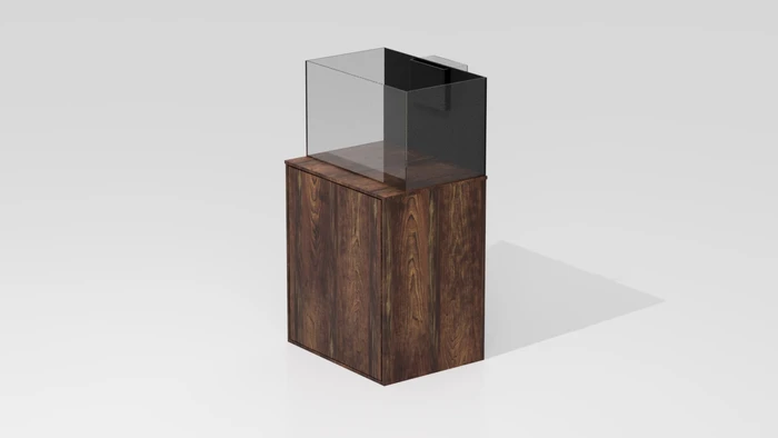
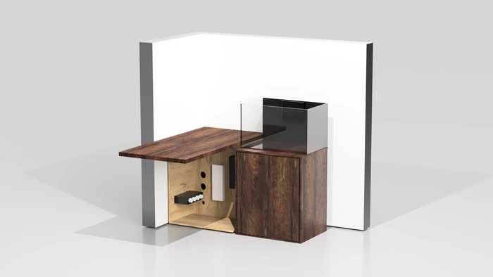
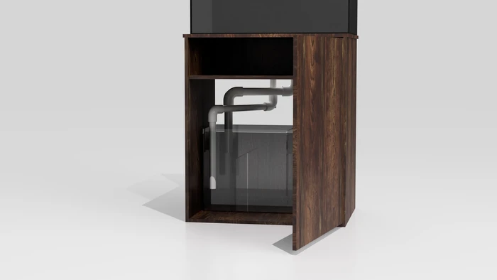
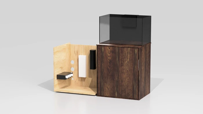
03 The numbers
How much water comes back down to the sump when the power goes out.
| Quantity | Value | How I got it |
|---|---|---|
| Drain-down volume in a power outage | 0.343 gal | When the pump stops, water siphons back down the return line until the tank level reaches the siphon-break hole, 0.25 in below the waterline. The UNS 60U is 23.15 × 13.7 in inside, so 23.15 × 13.7 × 0.25 = 79.3 in³, and 79.3 ÷ 231 in³/gal = 0.343 gal. |
04 Build
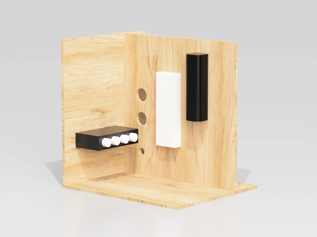
The equipment bay as I modeled it in Fusion 360.
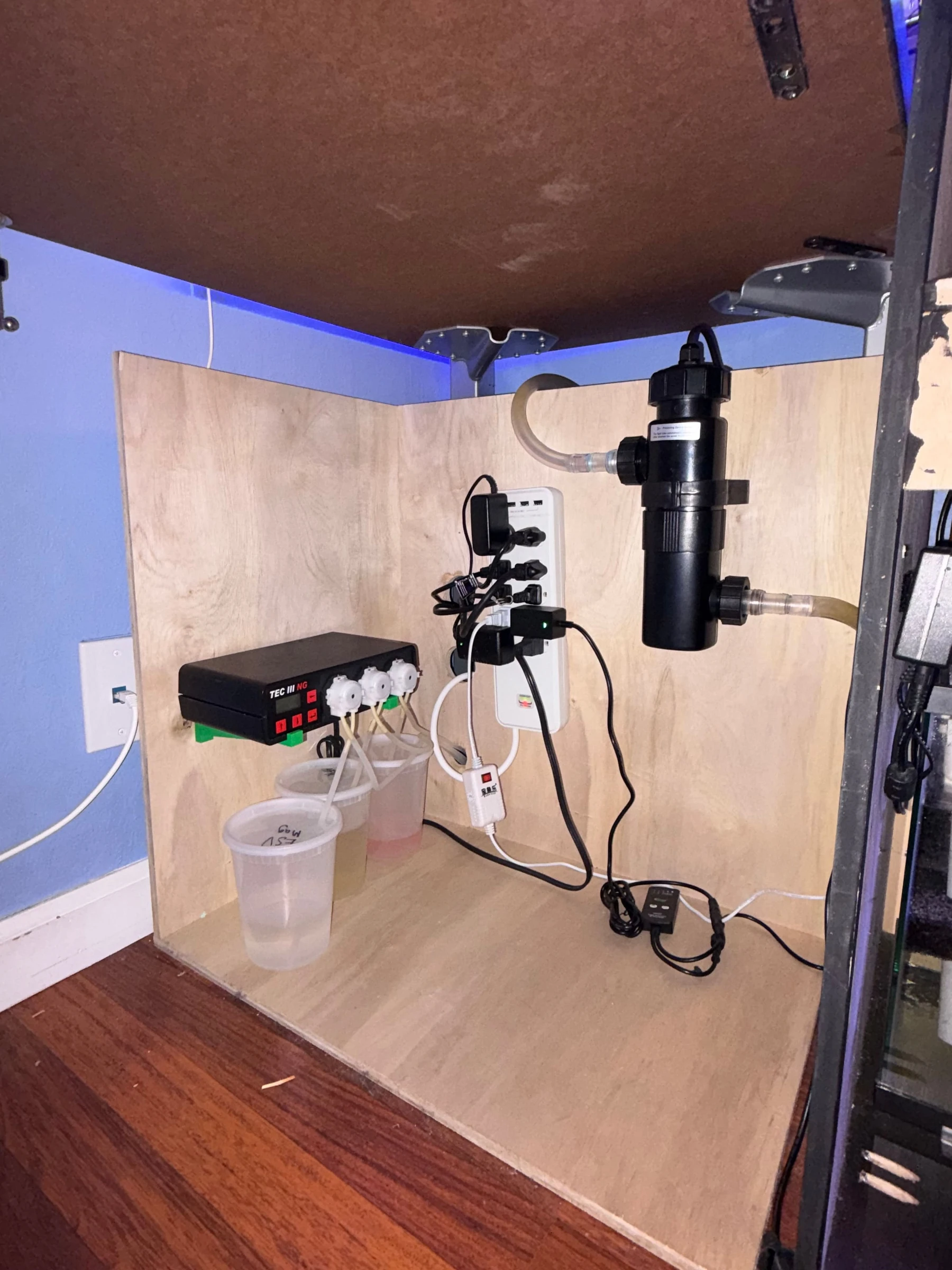
As built, with each piece where I placed it in the model. Left to right: a peristaltic doser dosing nitrate, alkalinity, and magnesium; the power strip; and a 9-watt UV sterilizer.
05 What failed and what I changed
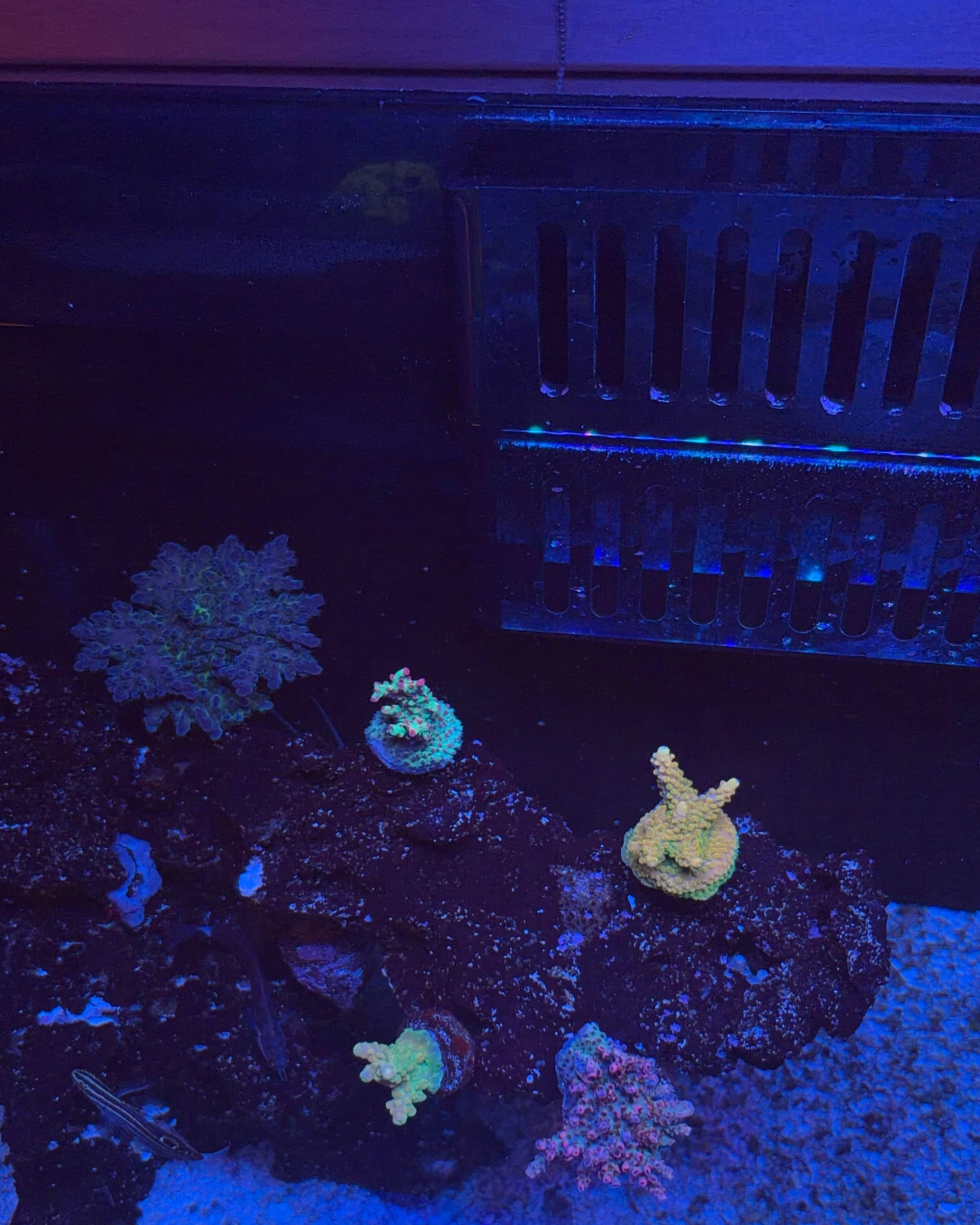
Microbubbles. Tiny air bubbles kept showing up in the display tank. I traced them to the return pump: when the water in the sump's return chamber ran low, the pump pulled in air and pushed it into the tank. I added a bubble trap to stop bubbles from moving across the sump and into the return.
Saltwater on the electronics. Saltwater spilled over my old surge protector. That's why I designed and built the equipment organizer: a separate bay beside the stand that keeps the electronics away from the water and the inside of the stand clean.
06 Result
It has never leaked, and it has been running since the day it was filled.
Next time I would build the equipment organizer sooner, before corrosion and spills had a chance to cause problems.